



Description
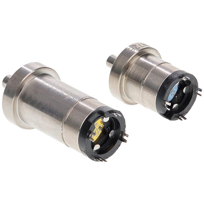
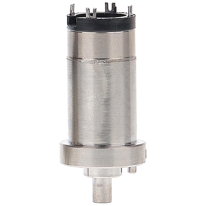
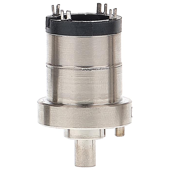
Force transducers (Series C) are designed for continuous proportional conversion of force into a proportional unnormalized electrical signal.
The transducers (sensors) are based on silicon strain gauges on a dielectric diaphragm and have high reproducibility of characteristics and long-term stability.
Force and pressure sensors with SOS (silicon-on-sapphire) technology are divided into two groups:
-
Group 3 – temperature-compensated with reduced dependence of the initial signal on temperature.
-
Group 4 – non-temperature-compensated with dependence of the initial signal on temperature.
The design of the force transducers, using a titanium alloy and a sensing element based on SOS structure, provides reliable devices with the following technical and operational characteristics:
-
High temperature stability of characteristics
-
Low hysteresis value
-
Wide operating temperature range
-
High output signal level
-
High overload capacity
-
High protection against aggressive media
Operating principle:
The sensing element is a dielectric diaphragm with silicon strain gauges. The diaphragm is rigidly connected over the entire surface with a titanium diaphragm, forming a two-layer diaphragm rigidly fixed in the housing. The two-layer diaphragm perceives the measured pressure (in a pressure transducer) or connects to a lever perceiving the measured force (in a force transducer).
Under the action of pressure or force, the diaphragm deforms, causing a change in the resistance of the strain gauges included in the bridge circuit. One diagonal of the bridge is powered, while the output electrical signal, proportional to the mechanical deformation of the diaphragm from applied pressure or force, is taken from the other diagonal.
Applications
For use in devices where it is necessary to convert force of non-aggressive to titanium, non-crystallizing (non-hardening) media into a proportional electrical signal:
-
Oil and gas industry
-
Chemical industry
-
Medical industry
-
Food industry
-
Public utilities
-
Military-industrial complex
Warranty period: for export – 18 months, in Russia – 54 months from the date of manufacture.
Mean time between failures (MTBF): not less than 400,000 h.
Average service life: not less than 12 years.
Additional Information
-
Using temperature-compensated transducers in pressure sensors reduces the initial additional temperature error, simplifying adjustment and providing highly stable devices.
-
Use of a thermistor in the design: D0.1 transducers can be manufactured with a thermistor for independent temperature measurements in the collector area with high accuracy.
Resistance requirements:
-
Sinusoidal vibration in the frequency range 10–150 Hz at acceleration 19.6 m/s² (2 g).
-
Multiple mechanical shocks with peak acceleration 98 m/s² (10 g), impulse duration 16 ms, and frequency 60–120 shocks per minute, 20 shocks in each position.
-
-
Mechanical loads with peak acceleration 147 m/s² (15 g), impulse duration 11 ms, frequency 60–120 shocks per minute, total 1000 shocks.
Characteristics
| Bridge Resistance Value, Must Be Within, kOhm | 4,50 +0,35 -0,50 гр.3/4,50 ±0,35 гр.4 |
| Degree of Protection Against Dust and Moisture per GOST 14254 | IP00 |
| Electrical Insulation Strength of Circuits Relative to Housing for 1 Minute Under Test Voltage, Frequency, Hz/Value, V | 45— 65/500 |
| Housing Materials | titanium alloy VD-9 |
| Initial Output Signal Value at Zero Parameter Value, Not Exceeding by Absolute Value, mV | 10 |
| Lever End Movement, Must Be Within, mm | 0,25 ±0,03 |
| Limit Temperature Range, °C | -60 +125 |
| Mechanical Impact Resistance and Strength Class (per GOST 12997-84) | V2 |
| Nominal Values of Converted Parameter for C Series, N | 5; 50 |
| Nominal Values of Converted Parameter for D Series, MPa | 0,1; 0,6; 2,5; 6,0; 16,0; 25,0; 40; 60,0; 100,0; 160 |
| Operating Temperature Range, °C | -50 +80 |
| Output Signal Change Range Corresponding to Nominal Parameter Value, Must Be Within, mV | 220 — 440 |
| Output Signal Nonlinearity in Normal Conditions, Not Exceeding, % of Output Signal Range | 0,15 |
| Output Signal Variation, Not Exceeding, % | 0,1 |
| Permissible DC Power Supply Voltage, Not Exceeding, V | 13 |
| Strain Gauge Electrical Circuit Insulation Resistance | up to 100 MΩ under normal conditions / up to 5 MΩ at 95±3% RH and 35±5 °C |
| Strain Gauge Mass, g | 35 |
| Strain Gauge Power Supply by DC Current, mA | 1,5 ±0,3 |
| Zero Signal Change in Operating Temperature Range by Absolute Value, Not Exceeding, mV/10 °C | 2.0 (Group 3) / 0.3 (Group 4) |